Observatory Construction
Construction of my backyard observatory started in 2016. The logistics concept was to stop at Home Depot on the way home from work on Fridays, buy what I needed for the weekend, and then work on Saturday. Another key was phasing the project where each stage ended at a useful and stable point where I could stop for some time period without having the project deteriorate due to weather. And of course here at 6900′ in New Mexico, weather can be anything from blazing sun to torrential rain, to significant snow.
Phase I – Pier & Observing Deck
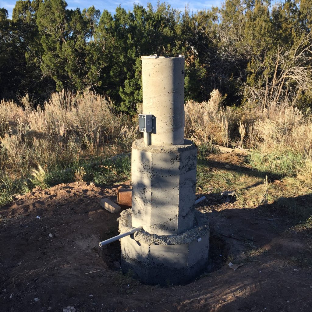
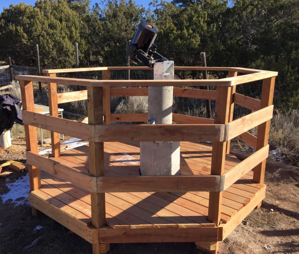
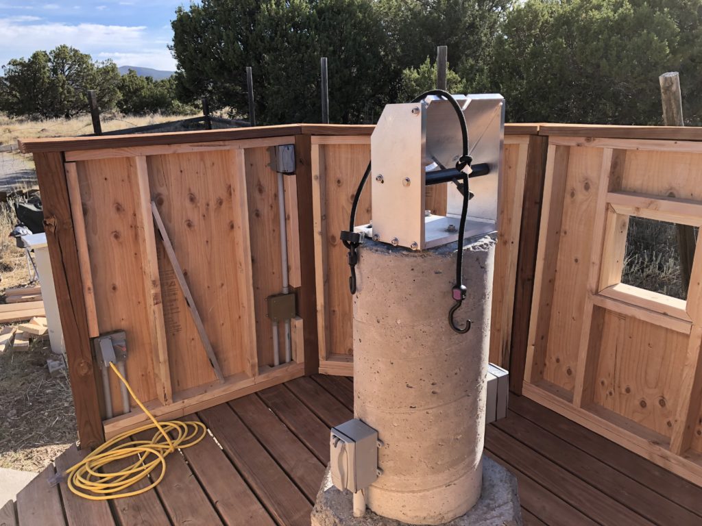
Started with pouring the pier. Ended up doing three pours. The first used a 12″ diameter form starting roughly three feet below grade and ending at a height of five feet. Several pieces of rebar to reinforce, and a 1/2″ thick aluminum mounting plate anchored to the top.
Once the concrete cured, the pier didn’t feel very steady when tapping and pushing at the top, so a second pour was done to add a 3 foot diameter footing around the base. After this, more tapping at the top still felt like there was a little too much vibration, so built a 2 foot diameter octagonal form and increased the pier diameter up half its height. The resulting pier is very stable with good, hard slaps to the top resulting in almost no vibration.
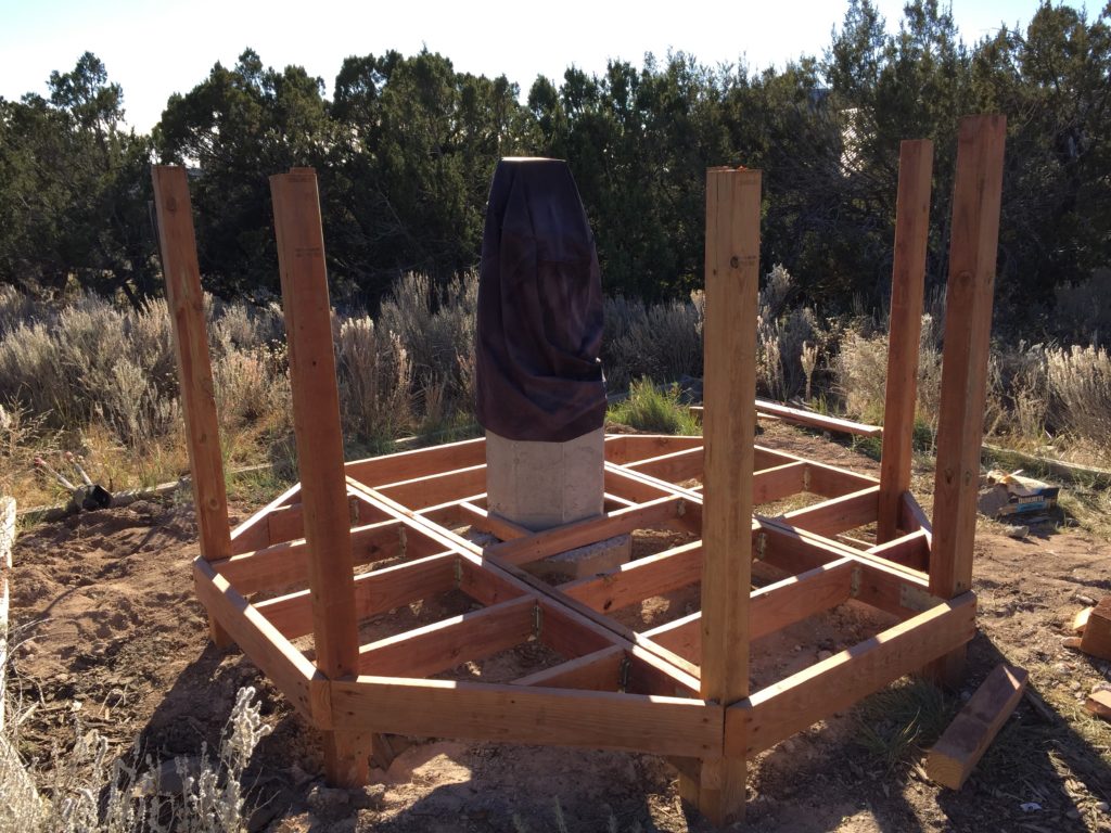
Then just built a deck around the pier. Pretty standard deck construction with 4×4 piers set into concrete filled holes, and then basic beam and joist framing covered with deck boards for the floor. Railings around the perimeter and the observing deck was complete.
Phase II – The Dome
With a very busy 2017, including getting ready for the “Great American Eclipse,” dome construction didn’t start until the early spring of 2018. Lots and lots of preliminary woodworking building the curved components for the dome. The plan was to have all of the components fabricated, then in early summer frame the base in a couple of weekends, followed by putting the dome up in a weekend plus a few days. Wanted to get the dome up and sealed before the late summer monsoon season.
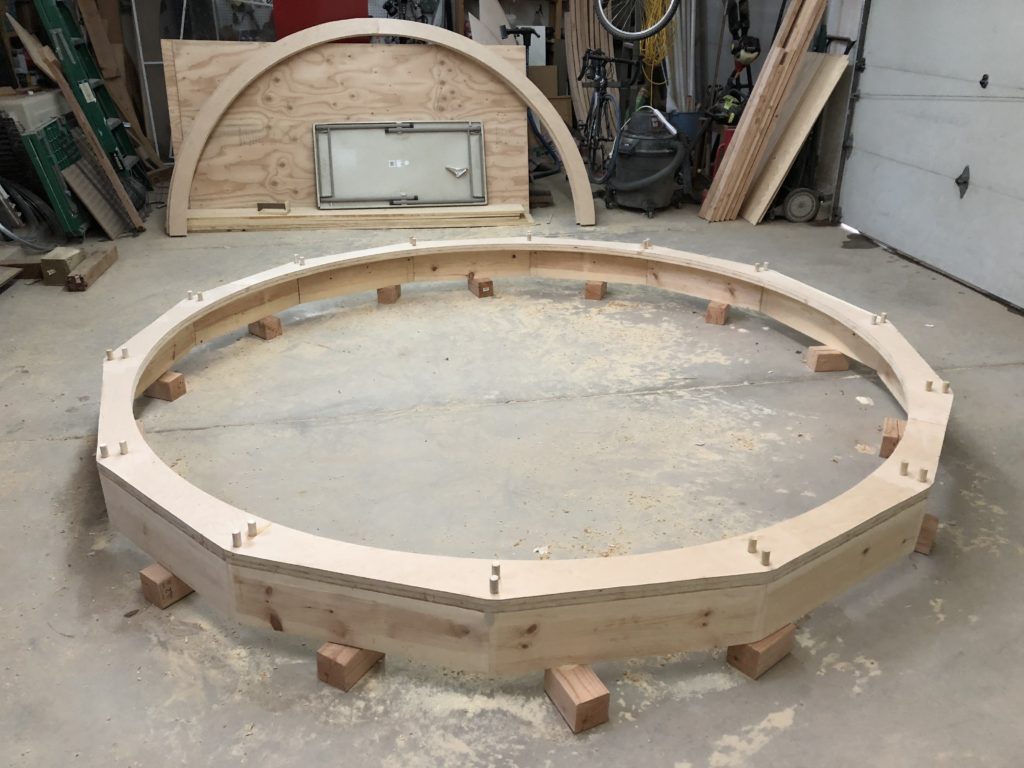
This is the base ring in the garage. I suppose another logistical requirement was to clear out the garage at the end of each weekend so we could get the cars back in. Got this vertical against the back wall of the garage shortly after taking this photo.
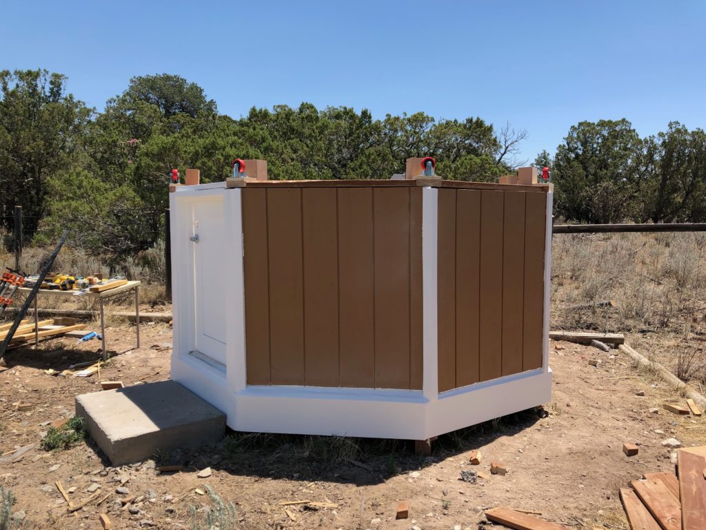
After getting all of the components fabricated, the next step was to frame and panel the base.
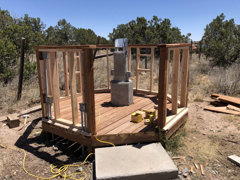
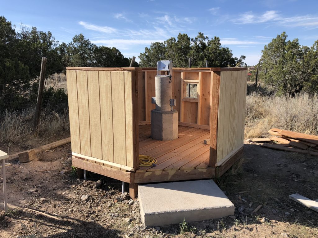
Final touches were to paint the sides, install the door, add the trim, and install the dome rollers on the top of the wall; specifically, on the top of the 4×4 supports so that the weight of the dome would be transmitted directly to the foundations.
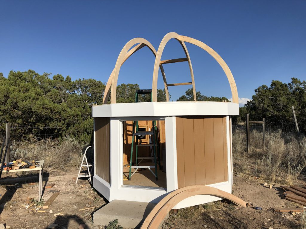
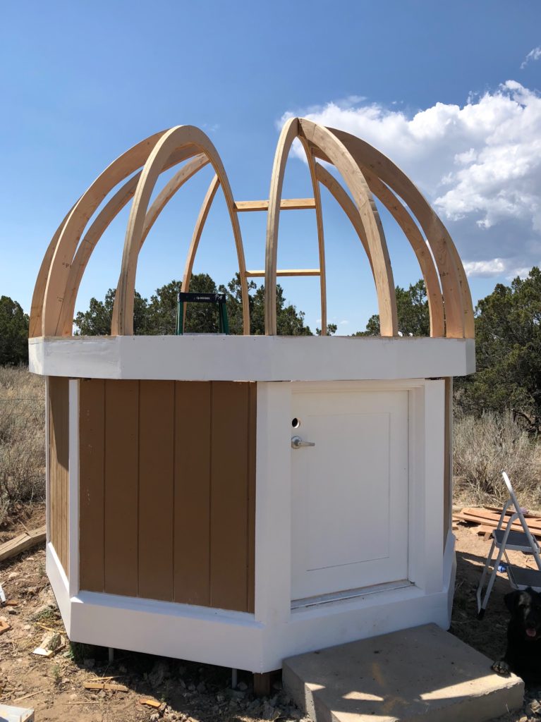
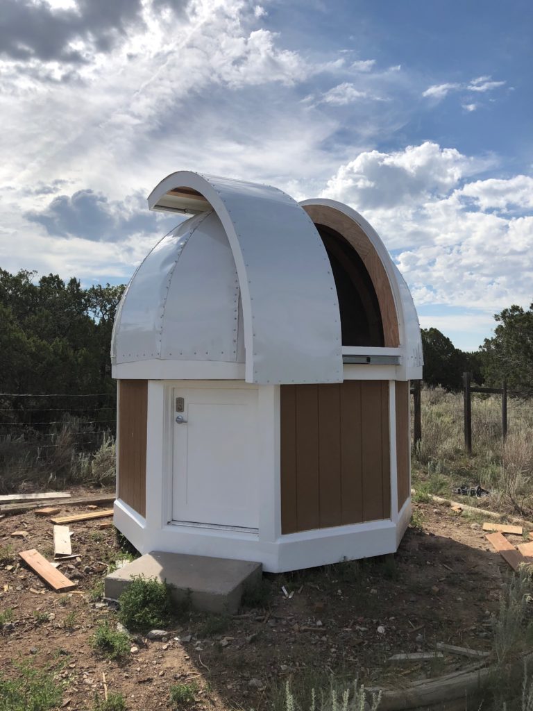
Finally ready to start putting the dome together. Starting with the base and the two arcs that frame the aperture, and then adding the rest of the framework.
Then cut and mounted the aluminum panels, and installed the shutter that I had previously fabricated. But this makes it all sound too easy. I had some issues with the “fold” on the edges of the aluminum panels. Having a large, curved press brake would have been a big help. And a couple of issues with process: how exactly to fasten the panels down without creating “wrinkles.” I had put some thought into this – each panel was nominally a section of a slightly elliptical cylinder, which is a shape that can be mapped to a plane – i.e. a flat sheet of aluminum – with no distortion. Just had a few minor issues with getting each panel screwed down uniformly without constraining some point in a “wrong” location. In the end, I had to pull off a couple of panels and replace them, which also required yet another trip to the sheet metal supplier. And there’s a pretty good amount of RTV silicone sealant filling some gaps and wrinkles. But, in the end, things turned out looking pretty good.
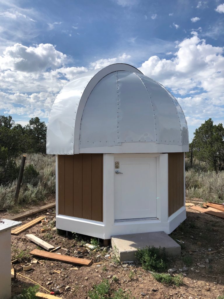
Just to fill in a couple of minor construction details… The shutter slides on two heavy-duty drawer glides, and I describe it as a 9-foot long, curved, inside-out drawer. And the little 4-foot high door was custom-made.
Phase III – Dome Control Electronics
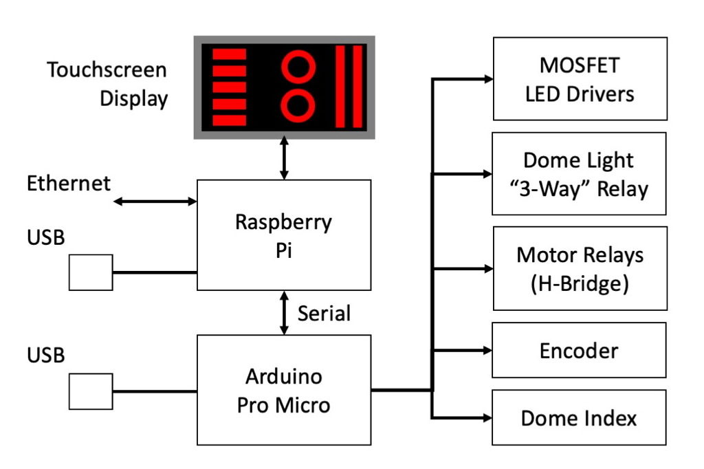
I’m using a Raspberry Pi and Arduino combination to provide the dome control. The Raspberry Pi takes care of the high-level interfaces, including a touchscreen display control panel and the network interfaces. The Arduino performs the low-level I/O tasks, interfacing to the dome’s incremental position encoder and optical indexing sensors, and driving the motor control relays, light switch relays, and MOSFET drivers for red LED strips. Here’s a top-level block diagram of the controller…
For basic telescope control, almost all planetarium software packages (Starry Night, TheSky, Stellarium, etc.) provide control for most GOTO telescope mounts. This is partly because most manufacturers implement either the Celestron or Meade control protocols. Primary differences center on the specific hardware interface, typically either looking for a Serial COM port (USB Serial) or a TCP/IP serial bridge, both of which are provided by the Losmandy mount. Coordination between the dome and telescope is implemented by having the dome “snoop” the telescope position; in this case through the TCP port.
Full observatory control will include integrating a camera, filter wheel, guider, and focuser. Since I’m more of a Linux/Mac mindset, this will be done using INDI/INDIGO – similar to the Windows-based ASCOM system. INDI provides a “Dome Scripting Gateway,” which interfaces to a dome controller through a set of Python scripts, allowing for a fairly “maker-friendly” way to incorporate the dome controls into an observatory control system, but more on this later.
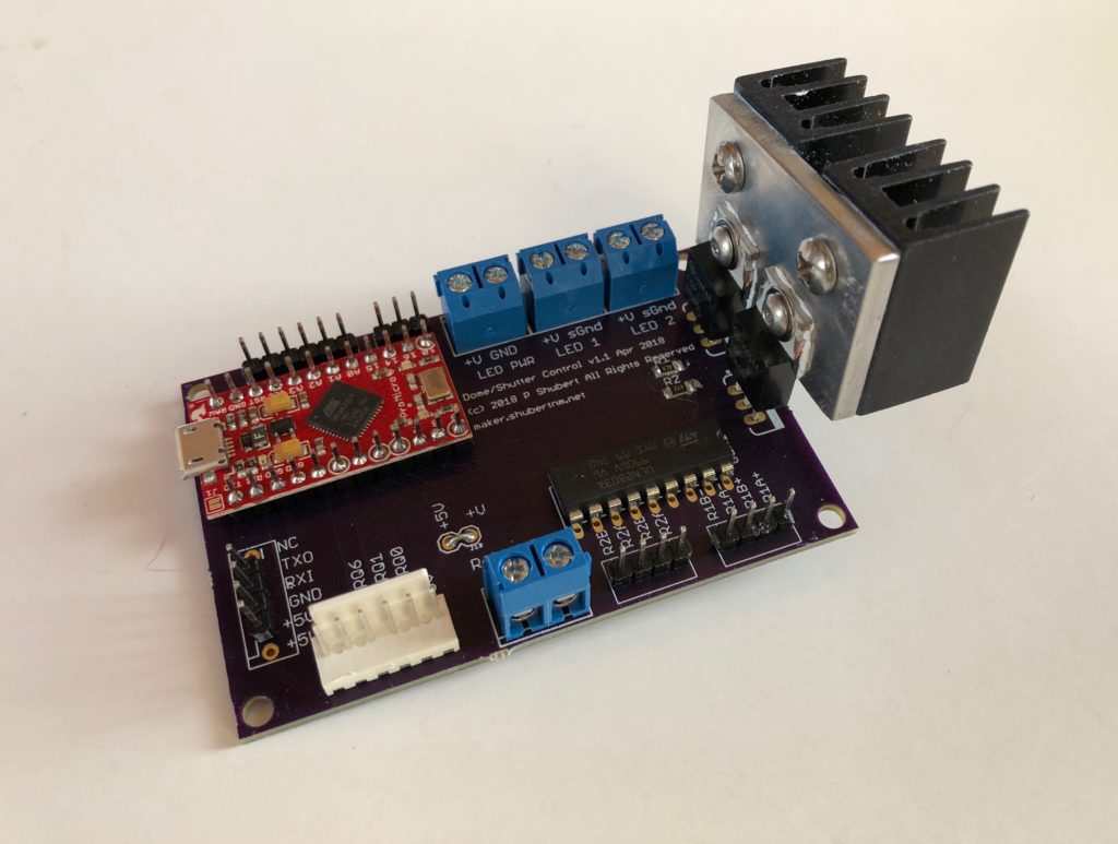
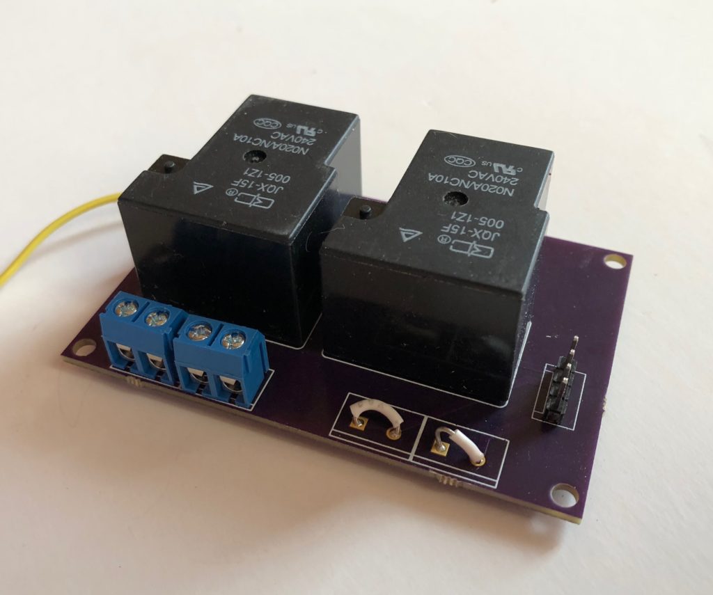
I built two printed circuit boards for the controller. The first mounted an Arduino Pro Micro and provided a relay driver and a pair of high current MOSFETS to drive red LED strip lights. The board also provided connections for power, LED wiring, relay wiring, encoder, index sensors, and a serial interface to the Raspberry Pi for command and control. The relay board mounted two high-power relays in an H-bridge configuration, along with power and motor wiring connections.
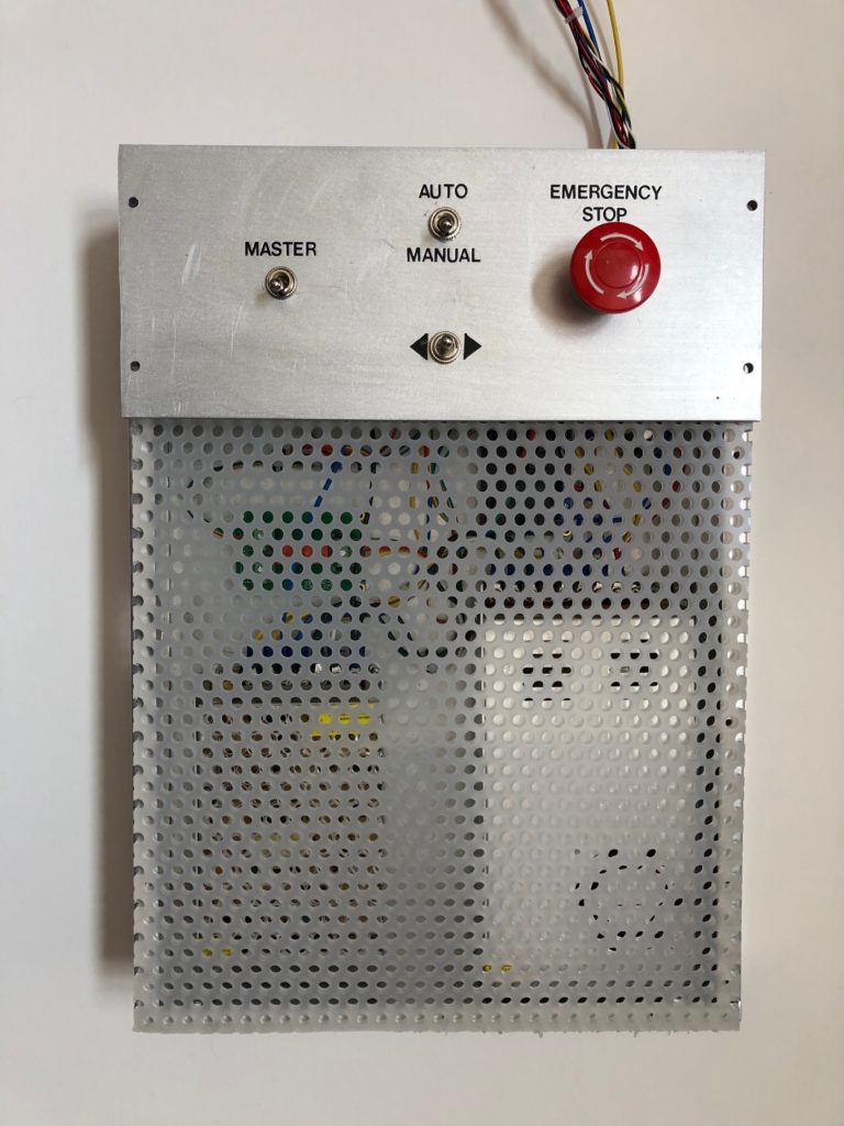
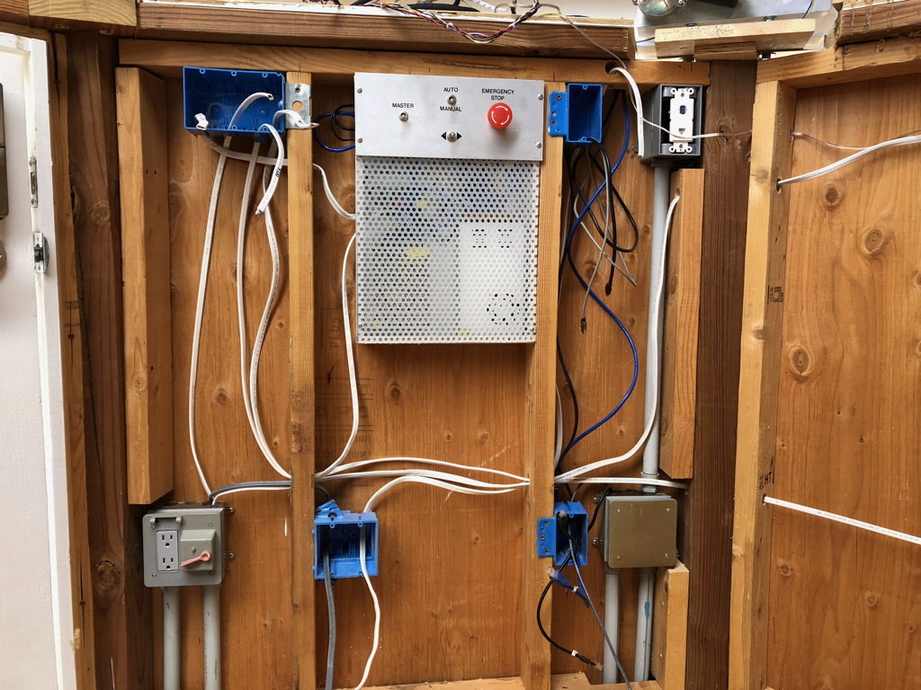
The custom PC boards were wired up in a Budd box along with the Raspberry Pi and power supplies; a 5V supply for the Arduino and Pi, and a high current 12V supply for the motor and LED lights. There’s a simple front panel to switch power on and off, and to provide complete manual control of the motor relays. The front panel includes an “Emergency Stop” button, which cuts power to the motor relays, and provides a logic signal to the Arduino and Pi to implement a soft stop for the telescope.
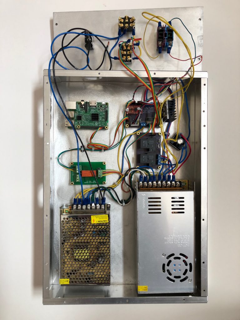
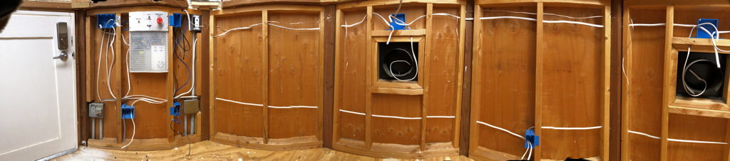
The box got installed between the studs in the observatory wall, along with all of the rough power wiring and data cables.
Phase IV – Interior Finishing
Pretty standard interior finishing: wallboard, tape, texture, & paint. Vinyl tile flooring. Floor moulding and finish electrical, including the data connections. A couple of wall cabinets for eyepiece and camera adapter storage. And, of course, an observing desk.
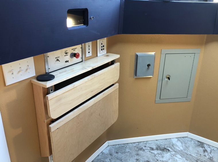
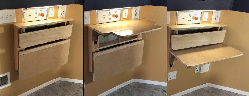
Pretty proud of the observing desk. Three configurations: all folded up against the wall, for maximum room in the somewhat small observatory, a counter-height surface for note-taking or working with a laptop/iPad while standing, and a standard desk-height surface.
Phase V – Integration & Telescope
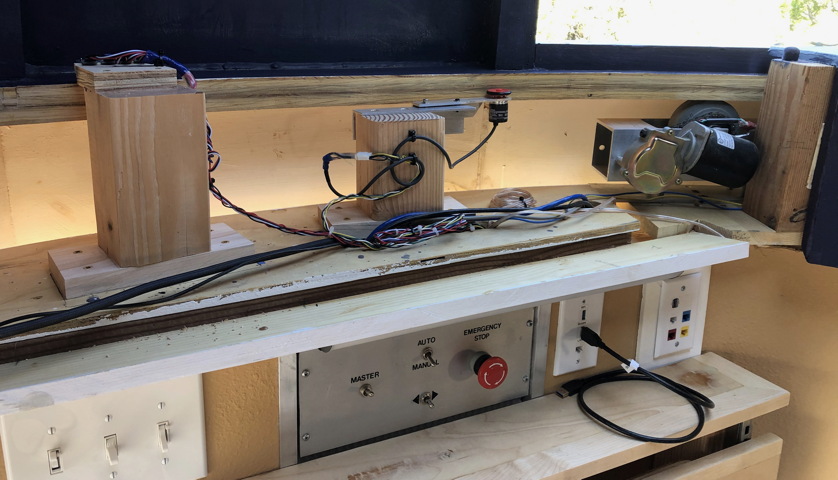
Finally! With all of the construction done, it was time to install the dome control components and get everything working. The control system consisted of: (left-to-right in the picture below) a set of IR reflective sensors, an incremental encoder rolling on the inside diameter of the dome, and the drive motor. The IR reflective sensors switched on reflective tape placed on the dome to provide an absolute index position. Dome motion was then sensed by the incremental encoder.
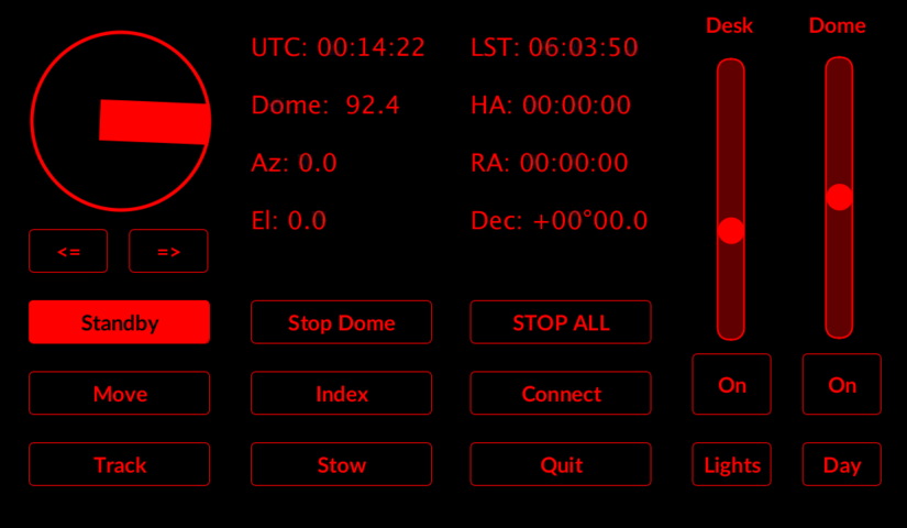
A touchscreen GUI provided the primary dome control interface. The GUI provides basic information to the operator, including time, and dome and telescope position. Slide controls allow dimming of the desk and dome red lights. A set of touch buttons control the connection to the telescope data interface and the dome control mode.
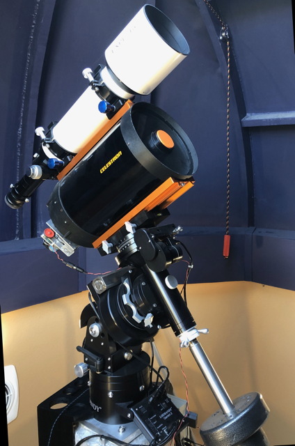
The mount is a Losmandy G11-GT with a Gemini controller. Currently using my existing telescope equipment, a Celestron 8″ SCT and an Explore Scientific 102mm ED triplet refractor. Future plans are to replace the 8″ with a Celestron C14. After getting the mount polar aligned I integrated the dome control electronics and mount with everything networked. There’s a wired ethernet network in the dome, along with a WiFi access point for local connectivity. The wired network runs back to the house via coax, where it attaches to the home network and internet through the home router and DSL connections. There are numerous telescope control options in addition to the hand controller, including a direct USB connection available at the observing desk and wired or wireless Ethernet through the observatory network. Generally, I use SkySafari on either my Mac or iPad to control the telescope, with the capability to either automatically move the dome to the telescope position, or have the dome continuously track the mount position.